
Building Types
40x60 Steel Workshop
- Width
- 40 ft
- Length
- 60 ft
- Floor area
- 2,400 sq ft
- Perimeter
- 200 ft
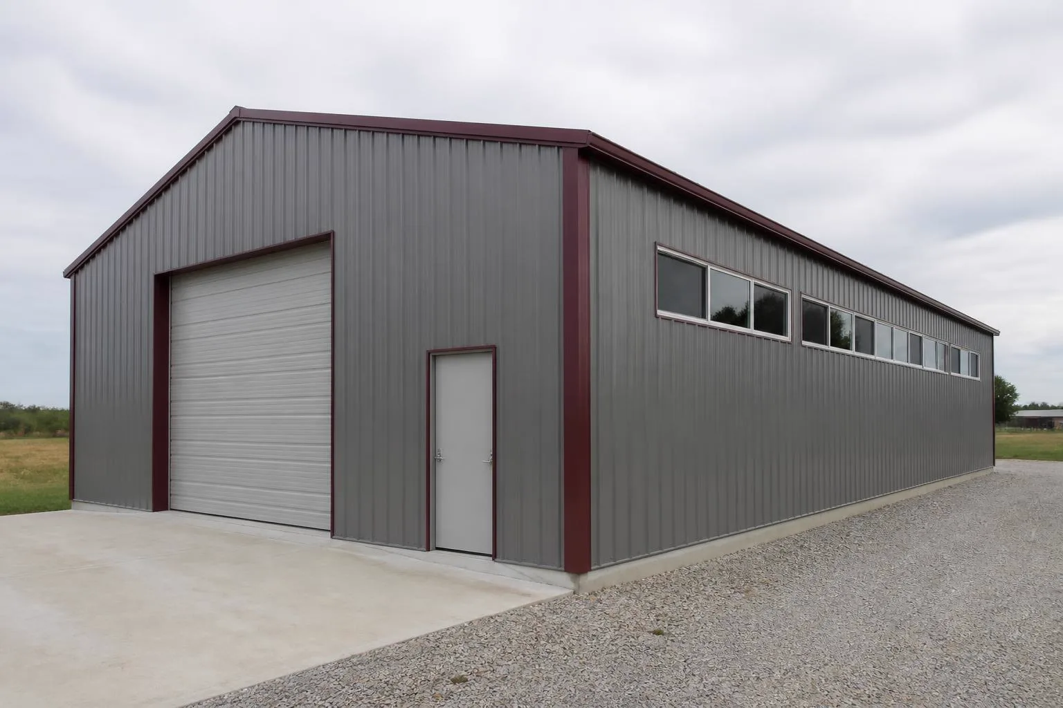
Configuration
How This Building Is Configured
A steel shop building specified around bench space, equipment clearance and door access.
Configuration summary
| Building type | Workshop |
|---|---|
| Footprint | 40 ft × 60 ft |
| Floor area | 2,400 sq ft |
| Eave height | 14 ft |
Example
Example Configuration
Quick dimensions
At a Glance
Width
40 ft across the gable end.
Length
60 ft along the sidewall.
Floor area
2,400 sq ft of clear floor.
Eave height
14 ft at the sidewall on the stored profile.
Access
Doors & Access Considerations
Opening width
Across a 40 ft gable end, the practical opening width is limited by the frame and confirmed with the supplier.
Opening height
A 14 ft eave sets the ceiling on door height before any frame change.
Drive-through
Matching openings at both ends avoid reversing, at the cost of usable wall.
Use
How a 40×60 Workshop May Be Used
Woodworking
Stationary machines need infeed and outfeed clearance, which drives usable length more than area.
Fabrication
An open central floor is commonly kept free so material can be moved and assembled.
Hobby shop
Separating a finishing area from cutting is a common planning decision at larger footprints.
Planning
Footprint & Space Planning
Footprint
Width and length are chosen together: width is usually fixed by what has to fit side by side, length by how many bays are needed.
Height
Eave height affects door options, storage height and how open the interior feels.
Access
Where vehicles and people enter changes the whole interior layout, so access is settled before anything else.
Doors and openings
Opening width, height and position are specified with the supplier; they affect the frame and the wall bracing.
Site
Slope, drainage, access for delivery and erection, and the foundation are confirmed for the actual property.
Expansion
Extending along the length is usually simpler than changing the width later, which is worth deciding up front.
Similar sizes
Other Sizes for a Workshop
Related
Related Building Types
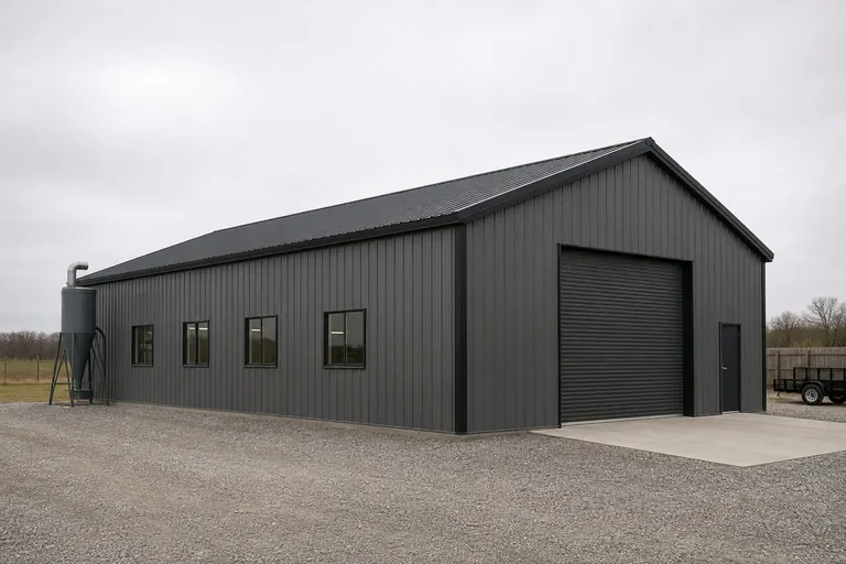
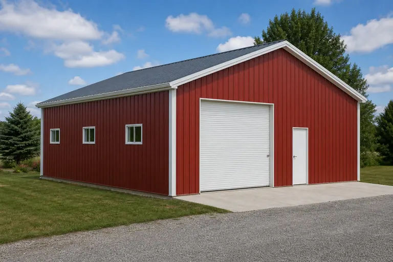
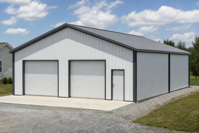
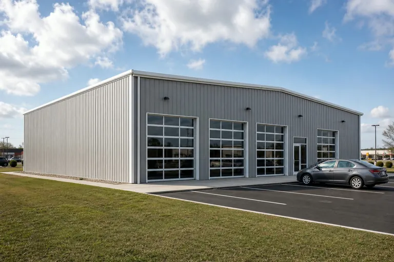
Example configuration — for planning purposes only.
FAQ
Common Questions
40 ft × 60 ft is 2,400 square feet of floor area before any interior partitions.
Length is usually adjusted in bay increments, and width is a larger design change. Both are confirmed with the supplier for the final design.
Site preparation, foundation and erection are commonly quoted separately from the building package. Confirm the scope of any quote you receive.
Cost drivers
Quantities that move the estimate at 40x60
No price appears on this page. The quantities that scale an estimate at 40x60 are 2,400 square feet of slab, 37 cubic yards of nominal concrete, 2,800 square feet of wall cladding and 2,474 square feet of roof cladding. The floor treatment is a use decision that outlasts most of the equipment standing on it.
Dock equipment, racking at both ends and any conveying or lifting equipment between process bays carry more of the estimate than general shell area, since the building's function depends on those connections.
- circuits and lighting beyond a garage standard
- extraction for the work done
- insulation and heating for long working sessions
- an opening large enough for materials and occasional vehicles
Overview
A 40x60 workshop planned as a shop planned around a straight path from bulk raw material to a finished-goods dock
This page is ordered around zone boundary, because that is the decision this footprint settles first and every later choice follows from it.
2 process bays fit across the 40-foot width with only 0 feet left over, which is a tight fit: the width is fully committed and nothing can be widened later without moving a wall.
Read this footprint through its span. 40 feet across is the fixed constraint; 60 feet of length is the negotiable one, and at 1.5 to 1 the building is close to square, so movement runs in both directions. The plan is only as good as the route into it, which is a site question rather than a building one.
A 40 by 60 footprint is a clearly directional plan: 2,400 sq ft enclosed by 200 ft of wall, at a 1.5:1 length-to-width proportion. Along its 60 ft dimension it takes 2 runs of process bays at 30 ft, leaving 0 ft over — the 0 ft is where the argument about this size actually happens. This mode treats the shop as a corridor between two states of the same material: bulk and raw at one end, boxed and finished at the other. The plan's whole logic is keeping those two ends from meeting anywhere except at the process bays between them. Electrical service, ventilation and fire separation for a working trade floor are determined for the specific building by the design professional and the authority having jurisdiction.
This footprint is planned as a shop planned around a straight path from bulk raw material to a finished-goods dock. Spent as a square 49 by 49 instead, the same 2,400 sq ft would stand 1 process bays across rather than 1, and would trade this plan's length for parallel access. That is the width-against-depth decision this footprint has already made. Compared with a 40 by 50 of the same width, the extra depth here adds run rather than reach: it buys about 2 process bays in line, and every position past the second is retrieved by moving what stands in front of it. At this scale the building is usually operated by one or two people who know where everything is, so the plan can be loose and the doors matter more than the divisions. The longest internal travel on a 40 by 60 plan is about 72 ft corner to corner, and the shortest useful one is the 40 ft cross-run. For a a shop planned around a straight path from bulk raw material to a finished-goods dock that matters where material flow shop planning sits, because shortening the 40 ft run to serve it lengthens every trip along the 60 ft dimension. Loading doors are sized for the largest vehicle or the longest stock the shop will ever move through them.
Areas, perimeter, roof area, ridge height, slab volume and the process bay counts on this page are computed from the stored 40x60 record and this platform's planning module for the workshop category.
Usable area
How the 2,400 square feet divides at 40x60
Computed process bay fit for a 40x60 workshop
| Measure | Computed at this footprint |
|---|---|
| Process bays across the 40-foot width | 2 at a 20-foot module |
| Leftover width | 0 ft (0 sq ft as a full-length strip) |
| Rows along the 60-foot length | 1 at a 30-foot module after 11 ft of circulation |
| Leftover depth | 19 ft (760 sq ft across the width) |
| Total process bays | 2 |
| Share of floor committed | 50% |
Module footprint used here is 20 by 30 feet, this platform's planning module for a workshop. It is not a code minimum or an engineered clearance.
Example allocation of the 60-foot length — planning model, not survey data
| Zone | Length along the building | Computed area |
|---|---|---|
| Work zone and benches | 27 ft | 1,080 sq ft |
| Machine and assembly floor | 21 ft | 840 sq ft |
| Material storage | 12 ft | 480 sq ft |
Shares applied to the stored 60-foot length; areas computed against the 40-foot width.
Module footprints and allocation shares come from this platform's use typology and are published as example planning models. They are not recommendations and do not describe a majority of projects.
Footprint arithmetic
The 40x60 footprint measured for a workshop
Computed dimensional profile of a 40x60 workshop
| Measure | Computed at this footprint |
|---|---|
| Floor area | 2,400 sq ft |
| Interior after a 2 ft wall strip | 36 × 56 ft (2,016 sq ft) |
| Proportion | 1.5 to 1 |
| Perimeter | 200 ft (83.3 ft per 1,000 sq ft of floor) |
| Wall carried against a square of the same area | +2% |
| Enclosed volume | 39,600 cu ft at a 14 ft eave and 19 ft ridge |
| Roof plane against floor | 2,474 sq ft (+3%) |
| Process bays planned | 2 across × 1 deep = 2 |
| Circulation and margin | 50% of the footprint |
| Widest clear opening planned | 32 ft on the 40 ft gable, 8 ft in a sidewall bay |
| Bay division | 5 bays at 12 ft (exact) |
Computed from the stored 40x60 record. The 2-foot wall strip, 4-foot corner margin and 4-foot pier allowance are this platform's planning conventions for reading a footprint; they are not code minimums or engineered clearances.
40 ft across takes 2 process bays and leaves 0 ft. With 1 ranks behind each other the width sets retrieval order: what goes in first comes out last.
The gable clears roughly 32 ft after corner framing: one opening, not two. The 60-ft sidewall takes up to 2 openings with piers between, which is where a second entry belongs.
60 ft divides exactly into 5 bays at 12 ft. Over 2,400 sq ft a single 12-ft grid is the difference between a plan and an accumulation.
19 ft survives at the end of the run — 760 sq ft across the full width. That is a zone to name before the frame is ordered, not a leftover to discover after it.
At 14 ft a 12-ft platform across 40 ft would add about 480 sq ft. Framing for it now is a drawing change; adding it to a finished frame is a structural one.
200 ft of wall encloses 2,400 sq ft, against 196 ft for a square of the same area — a 2% difference. Little of the enclosure exists only because of the shape.
How the 60-foot run can be divided
| Bays | Spacing | Division | What it means for the plan |
|---|---|---|---|
| 5 | 12 ft | Exact | 60 divides exactly by 12, so the frame line, the sidewall openings and any interior division can all land on the same grid. |
| 6 | 10 ft | Exact | 60 divides exactly by 10, so the frame line, the sidewall openings and any interior division can all land on the same grid. |
| 3 | 20 ft | Exact | 60 divides exactly by 20, so the frame line, the sidewall openings and any interior division can all land on the same grid. |
Bay divisions are arithmetic on the stored 60-foot length. Frame spacing for a specific building is set by the manufacturer's engineering, not by this table.
Allocation
Dividing the floor for a shop planned around a straight path from bulk raw material to a finished-goods dock
The shop pattern this footprint could equally be organised around is one floor divided among several trades that each need their own zone but share the building: there is no neutral cross-aisle, so reaching one trade zone means walking through another one's working floor. Bulk receiving and raw storage occupy one end, process bays occupy the middle in the sequence material actually passes through, and finished-goods staging and a shipping dock occupy the far end.
Because 19 feet clears the 12 feet this platform treats as usable, the end of the run is a room rather than a gap: 760 square feet for a receiving apron on one end and a shipping apron on the other, kept as two separate exterior areas rather than one shared yard. Whoever operates the building daily should read the plan before it is frozen, because they know where the pinch points are.
Only 0 feet of width is spare, so there is no wall strip: anything set along a sidewall comes out of a process bay's clearance. Daylight placement changes how a floor is used far more than its cost suggests.
Spent as a square 49 by 49 instead, the same 2,400 sq ft would stand 1 process bays across rather than 1, and would trade this plan's length for parallel access. That is the width-against-depth decision this footprint has already made. Compared with a 40 by 50 of the same width, the extra depth here adds run rather than reach: it buys about 2 process bays in line, and every position past the second is retrieved by moving what stands in front of it. At this scale the building is usually operated by one or two people who know where everything is, so the plan can be loose and the doors matter more than the divisions. The longest internal travel on a 40 by 60 plan is about 72 ft corner to corner, and the shortest useful one is the 40 ft cross-run. For a a shop planned around a straight path from bulk raw material to a finished-goods dock that matters where material flow shop planning sits, because shortening the 40 ft run to serve it lengthens every trip along the 60 ft dimension. Loading doors are sized for the largest vehicle or the longest stock the shop will ever move through them. That movement pattern, not the 2,400-square-foot total, is what decides whether the leftover 19 feet is useful here.
Configurations
Configuring 2 process bays at 40x60
Nominal bay division computes to 3 bays at about 20 feet, wider than the 20-foot module — so a position can sit inside a bay without a frame line splitting it. Security and after-hours access are easier to design in the door layout than to bolt on later.
One row deep keeps the layout honest — no aisle to protect, no rear zone to serve, and the full 60-foot length available along the wall. The span is the commitment; everything inside it is rearrangeable later, and the 40-foot dimension is not.
Extension is cheapest along the 60 ft dimension, where each added bay repeats work already framed; widening past 40 ft is a different frame rather than a longer one. Growing to 40 by 90 adds a 3th run of process bays — useful if the constraint is process bays rather than the 0 ft already spare at the far end.
Configured as a shop planned around a straight path from bulk raw material to a finished-goods dock, 40x60 is judged on whether the 2 process bays it holds match the operation, and on whether the 0 feet of spare width leaves the route this mode depends on.
- Does the work need three parked lanes, or two lanes and a moving lane wide enough for equipment to pass, or does it need a second lane that this 40-foot span cannot give?
- Is the 60-foot length being bought for depth, or for the repeated bays — five or six repeated bays, so functions are assigned bay by bay?
- How much bench length do you need, and which wall can give it?
- What is the largest thing that has to come in through the door?
Bay division shown here is a planning module computed from the stored length. Actual bay spacing is set by the manufacturer's frame design for the building.
Height
Interior height for a 40x60 workshop
Across a 40-foot span the 3:12 pitch adds 5 feet between eave and ridge. The centreline measures 19 feet; anything parked or stacked near a wall lives with the 14-foot eave. Doors and their approaches decide more about daily use here than the enclosed area does.
Height on a 40 ft span is a separate decision from the 60 ft length, and it is the span that sets the frame's behavior. Raising the eave over 2,400 sq ft affects every bay along the 60 ft dimension, so the test is whether material flow shop planning genuinely needs the extra clear height or only the floor area.
Ventilation across 2,400 square feet at this height: dust and fumes from the work done, which argues for a planned extraction point rather than an open door.
Clear height below purlins, bracing and lighting is lower than the eave height. The usable figure comes from the manufacturer's framing for the selected building.
Openings
Openings for 2 process bays across
At 40 feet the gable will not comfortably take one opening per process bay: 2 positions with 0 feet spare leaves too little wall for piers. A single wider opening, or a sidewall opening, is the workable route. The building is fixed for decades while the operation inside it changes every few years, and the plan has to survive that.
A receiving door at one end and a shipping door at the other are functionally different even when they look similar, and combining them into a single door creates the exact bottleneck the layout is meant to avoid.
Framed-opening sizes, headers and the structure around them are engineered for the specific building. Confirm every opening with the door supplier and the building manufacturer before ordering.
Comparison
What changes at adjacent footprints
Computed comparison of nearby footprints for a workshop
| Footprint | Floor area | Process bays |
|---|---|---|
| 24x40 | 960 sq ft | 1 (1 x 1) |
| 20x50 | 1,000 sq ft | 1 (1 x 1) |
| 25x40 | 1,000 sq ft | 0 (1 x 0) |
| 30x35 | 1,050 sq ft | 0 (1 x 0) |
| 30x36 | 1,080 sq ft | 0 (1 x 0) |
Areas computed from each stored size record; process bay counts computed with the same 20 by 30 foot planning module.
- 24x40 moves the count from 2 to 1 process bays (1 across by 1 deep), which is the reason to choose between them.
- 20x50 moves the count from 2 to 1 process bays (1 across by 1 deep), which is the reason to choose between them.
- 25x40 moves the count from 2 to 0 process bays (1 across by 0 deep), which is the reason to choose between them.
Nearby footprints read for a workshop: exact change in area and in planning process bays
| Footprint | Area Δ | % Δ | Process bays at that footprint | What changes for this use |
|---|---|---|---|---|
| 50x50 | +100 sq ft | +4.2% | 2 (2 x 1) | Same process bay count on this planning module; the difference is circulation and stored depth, not capacity. |
| 36x60 | −240 sq ft | −10% | 1 (1 x 1) | −1 process bay on the same planning module. |
| 40x70 | +400 sq ft | +16.7% | 1 (1 x 1) | −1 process bay on the same planning module. |
| 40x50 | −400 sq ft | −16.7% | 1 (1 x 1) | −1 process bay on the same planning module. |
Areas are arithmetic on two stored size records; process bay counts use this platform's 20 by 30 foot planning module and are not a capacity statement.
Because this footprint is planned as a shop planned around a straight path from bulk raw material to a finished-goods dock, the useful next reads are different from the ones a differently shaped workshop suggests: material flow shop planning, receiving and shipping layout, process bay sequence.
Step economics
Going bigger or smaller than 40x60: what each step actually buys
One module step in each direction from 40x60, read for a workshop
| Footprint | Floor area | Process bays | Wall line | Floor bought per added foot of wall line |
|---|---|---|---|---|
| 40 x 60 ft (this page) | 2,400 sq ft | 2 (2 x 1) | 200 ft | — |
| 40 x 90 ft (one module deeper) | 3,600 sq ft (+1,200) | 4 (2 x 2) | 260 ft (+60) | 20 sq ft per added foot of wall line |
| 60 x 60 ft (one module wider) | 3,600 sq ft (+1,200) | 8 (4 x 2) | 240 ft (+40) | 30 sq ft per added foot of wall line |
Arithmetic on the stored 40x60 record and on this platform's 20 by 30 foot planning module. Wall line is perimeter, used as a proxy for enclosure quantity only; it is not a price and not an engineered quantity.
At 40 by 60 the building is narrow relative to its run, so the efficient direction of growth is across rather than along: 20 feet of extra width returns 1,200 square feet against 40 feet of added wall line (30 square feet per foot), where a 30-foot module of depth returns 1,200 for 60 feet (20). The caveat is structural rather than arithmetic — widening changes the clear span and the frame that carries it, while lengthening only repeats a frame line that already exists.
Both steps buy capacity here: one more module of depth takes the plan from 2 to 4 process bays, and 20 feet of width takes it to 8. Where they differ is in what they do to the interior — the deeper building adds a new row behind the existing one and lengthens every internal route, while the wider building adds a full-length process bay that can be entered on its own from the gable end.
The binding dimension is the depth. The 40-foot width absorbs its 2 process bays with 0 feet spare (0 square feet down the length), while the length leaves 19 feet after 1 module and 11 feet of circulation — 760 square feet across the full width. That is a genuine end zone rather than a margin, and it is worth planning it as a receiving apron on one end and a shipping apron on the other, kept as two separate exterior areas rather than one shared yard before the interior is fixed.
Access works from the gable end at this footprint. 30 feet of the 60-foot run is uncommitted once 1 module of depth are placed, which is more than the 22 feet this platform plans a square-on approach around, so each of the 2 positions across the 40-foot width can be reached without moving what is beside it. That is the difference between a building that is loaded and one that is unpacked.
Visualization
Reading the 40x60 footprint as a workshop
FAQ
Questions about 40x60 workshop projects
Take 2 ft off each wall as a working strip and the plan area drops from 2,400 to about 2,016 sq ft across 36 by 56 ft. Against that, 2 by 1 process bays occupy 1,200 sq ft and roughly 50% of the footprint stays as movement and margin. That circulation share is the number worth arguing about; the headline area is not.
The 40-ft gable takes an opening of about 32 ft clear after corner framing — 1 module-width opening. The 60-ft sidewall takes up to 2 spaced with piers, and those piers sit naturally on the 5-bay grid at 12 ft. Openings are planning geometry here; the sizes a specific building can actually carry come from the manufacturer's engineering for that frame.
One more bay at 12 ft adds 480 sq ft, 20% more floor, and keeps the clean division. It buys depth, not span: if the constraint is fitting things side by side, extra length does not solve it.
Measured on this footprint, 30 more feet of depth adds 1,200 square feet for 60 feet of extra wall line and 20 more feet of width adds 1,200 square feet for 40 feet. Width is the cheaper floor, but width is also the dimension that changes the clear span, so the two are not interchangeable decisions. Capacity moves from 2 to 4 process bays if you go deeper and to 8 if you go wider.
A 5-inch slab across 2,400 square feet computes to 37 cubic yards before thickened edges, piers or waste. The final design comes from the foundation engineer.
Reserving 11 ft across the 40 ft dimension for movement leaves 29 ft of working width, which takes 1 process bays at 20 ft. Along 60 ft it takes 2 runs at 30 ft. That is 2 positions out of 2,400 sq ft, and the remainder is circulation, walls and the margin every plan needs. Whether that count is enough depends on do raw material and finished product enter and leave through different ends of the building, or through the same door. These are planning figures computed from the footprint, not a quoted layout.
2,800 square feet of wall and 2,474 square feet of roof at a 3:12 pitch — the roof exceeding the floor by 3%.
2 process bays at this platform's 20 by 30 foot planning module commit 1,200 of the 2,400 square feet. The rest is 0 feet of width margin (0 square feet), 19 feet of end depth (760 square feet) and 11 feet of circulation. These are planning figures for reading the footprint, not engineered clearances.
As many as the actual sequence requires and no more, since every bay added out of sequence is a place material can be set down and forgotten rather than moved forward.
The width leaves 0 feet spare after 2 process bays. There is no margin, so added equipment or wall storage comes out of a position. Width is the dimension that cannot be extended later.
Methodology
How this page was produced
Sources and methodology
Find Steel Buildings dimensional records
Find Steel Buildings · Primary platform dataset · Tier 1 — code authority, standards body, primary dataset or manufacturer engineering
Supports: Stored nominal width, length, eave height, roof pitch and slab thickness for this subject.
International Building Code and International Residential Code
International Code Council · Model code · Tier 1 — code authority, standards body, primary dataset or manufacturer engineering
Supports: The framework of adopted codes and local amendments that decides permitting, separation and opening requirements. Cited as the governing framework, never as a local requirement.
- Dimensional figures: Width, length, eave height, roof pitch and nominal slab thickness come from this platform's stored record for the subject. Floor area, perimeter, wall area, roof area, ridge height and slab volume are computed from those inputs rather than transcribed.
- Process bay fit: Counts, leftover strips and per-module areas are computed from the stored 40x60 record against this platform's 20 by 30 foot planning module for the workshop category, with 11 feet allowed for circulation. The module is editorial planning typology, not a code minimum or an engineered clearance.
- Allocation model: Zone shares come from this platform's use typology for workshop and hobby space and are applied arithmetically to the stored 60-foot length.
- Allocation and layout models: Layout splits are arithmetic on the stored footprint, published as example allocation models. They are not survey findings and do not describe what buyers most often choose.
- Clearance and opening guidance: Clearance and opening statements are planning guidance. Final dimensions depend on the selected door system, header detail and the manufacturer's engineering for the building.
Methodology notes
- Prices: No price figure appears on this page. Cost data is published on this platform only with a documented inclusion basis, a collection date and a named source.
Drawn to scale
Plans and dimensions
Every drawing below is generated from the exact dimensions for this building, so proportions and areas are accurate.
Continue your research
Related planning topics
Background reading on the questions this page raises. None of these pages sells anything.
Compare 40x60 workshop configurations
Review the allocation models for this footprint side by side, then estimate the configuration you intend to build.