Building Types
80x120 Industrial Steel Building
- Width
- 80 ft
- Length
- 120 ft
- Floor area
- 9,600 sq ft
- Perimeter
- 400 ft
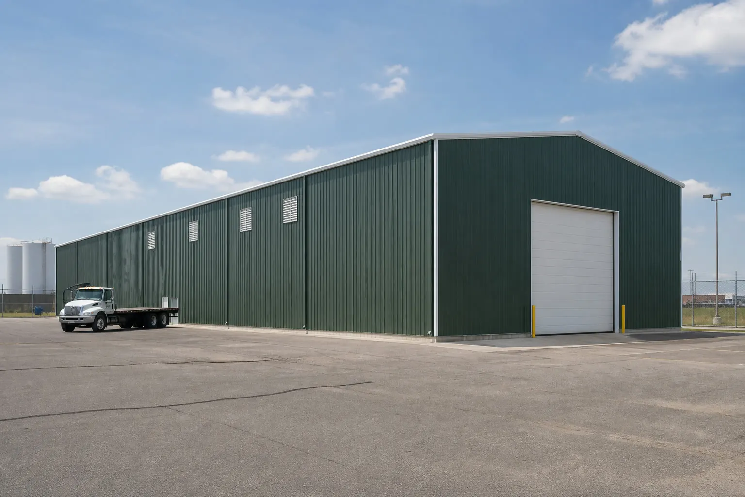
Quick dimensions
At a Glance
Width
80 ft across the gable end.
Length
120 ft along the sidewall.
Floor area
9,600 sq ft of clear floor.
Eave height
22 ft at the sidewall on the stored profile.
Configuration
How This Building Is Configured
Configuration summary
| Building type | Industrial Building |
|---|---|
| Footprint | 80 ft × 120 ft |
| Floor area | 9,600 sq ft |
| Eave height | 22 ft |
Planning
Footprint & Space Planning
Footprint
Width and length are chosen together: width is usually fixed by what has to fit side by side, length by how many bays are needed.
Height
Eave height is commonly the governing dimension here, because clearance for the tallest item sets the door and the wall.
Access
Where vehicles and people enter changes the whole interior layout, so access is settled before anything else.
Doors and openings
Opening width, height and position are specified with the supplier; they affect the frame and the wall bracing.
Site
Slope, drainage, access for delivery and erection, and the foundation are confirmed for the actual property.
Expansion
Extending along the length is usually simpler than changing the width later, which is worth deciding up front.
Use
How a 80×120 Industrial Building May Be Used
Production or storage flow
Material entering one end and leaving the other is a common organising principle.
Loading access
Dock or grade-level door placement is usually decided before the frame layout.
Racking and clear height
Usable stacking height depends on eave height and any interior structure.
Equipment and services
Power, compressed air and lighting layouts follow the bay spacing.
Example
Example Configuration
Access
Doors & Access Considerations
Opening width
Across a 80 ft gable end, the practical opening width is limited by the frame and confirmed with the supplier.
Opening height
A 22 ft eave sets the ceiling on door height before any frame change.
Drive-through
Matching openings at both ends avoid reversing, at the cost of usable wall.
Similar sizes
Other Sizes for a Industrial Building
80′ × 100′
8,000 sq ft
80′ × 140′
11,200 sq ft
70′ × 120′
8,400 sq ft
Related
Related Building Types
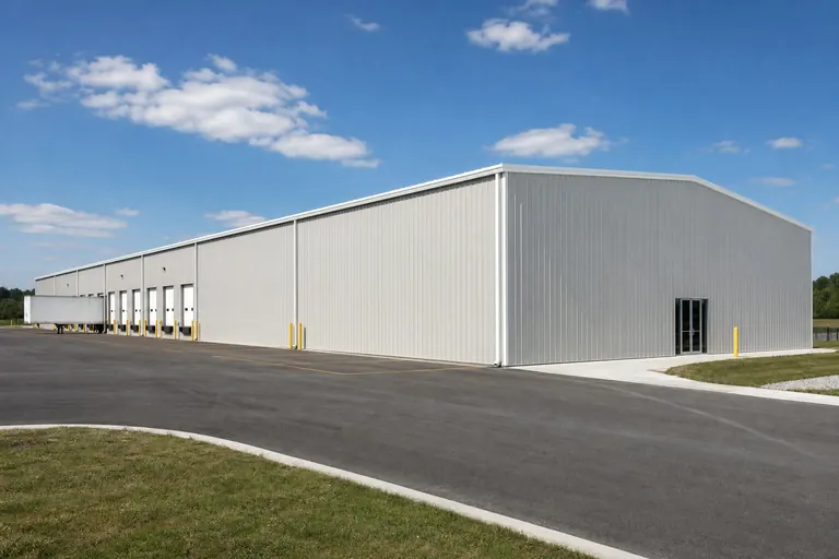
Warehouse
Explore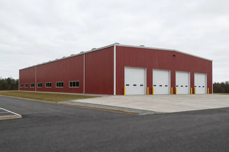
Manufacturing Building
Explore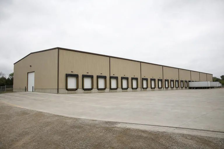
Distribution Center
Explore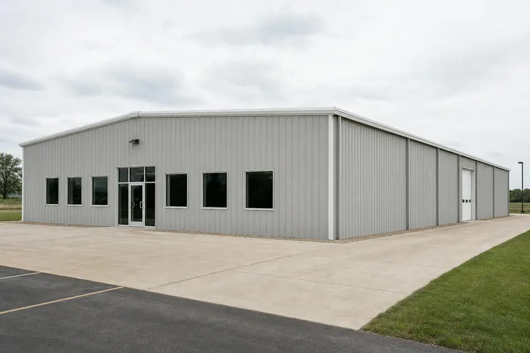
Commercial Building
Explore
Example configuration — for planning purposes only.
FAQ
Common Questions
80 ft × 120 ft is 9,600 square feet of floor area before any interior partitions.
Length is usually adjusted in bay increments, and width is a larger design change. Both are confirmed with the supplier for the final design.
Site preparation, foundation and erection are commonly quoted separately from the building package. Confirm the scope of any quote you receive.
Compare nearby sizes
Related footprints for this building type
Each page works through one footprint for one building type.
Overview
A 80x120 industrial building planned as a floor planned around heavy static and moving loads
This page is ordered around where the heavy loads stand and how they travel, because those two decisions govern the slab, the route and the rest of the plan.
The footprint holds 4 load positions — 2 across by 2 deep — and leaves 12 feet of depth for a laydown margin where heavy items wait before and after they occupy a load position.
Commitment first: 53% of the 9,600 square feet goes to load positions at 1260 square feet each, and 3,840 square feet survives as edge strip. A footprint is worth its own decision when that split lands where the work does. Cleaning, maintenance and inspection all need reach, and reach is planned in the gaps rather than in the modules.
A 80 by 120 footprint is a clearly directional plan: 9,600 sq ft enclosed by 400 ft of wall, at a 1.5:1 length-to-width proportion. Along its 120 ft dimension it takes 2 runs of load positions at 45 ft, leaving 30 ft over — the 30 ft is where the argument about this size actually happens. Taken purely as arithmetic, 80 by 120 gives 2 load positions across the 80 ft dimension once 18 ft is reserved for movement, and 2 deep along the 120 ft dimension. Run as a a floor planned around heavy static and moving loads, 6 ft across is below the 12 ft this use needs to be worth planning, so there is no laydown margin, so items wait in the travel route and the floor is congested whenever two moves overlap The largest item that will ever enter the building sets the opening, and that item is rarely the one described at briefing.
This footprint is planned as a floor planned around heavy static and moving loads. Spent as a square 98 by 98 instead, the same 9,600 sq ft would stand 2 load positions across rather than 2, and would trade this plan's length for parallel access. That is the width-against-depth decision this footprint has already made. Compared with a 80 by 90 of the same width, the extra depth here adds run rather than reach: it buys about 2 load positions in line, and every position past the second is retrieved by moving what stands in front of it. A building of this size behaves like a small yard under a roof: zones need to be defined, signed and left alone, or they migrate. Movement is infrequent, deliberate and disruptive: when a heavy item moves, other work stops. The plan earns its keep by shortening that route rather than by adding area. The apron outside the doors takes more punishment than the floor inside them and is more often under-specified.
Areas, perimeter, roof area, ridge height, slab volume and the load position counts on this page are computed from the stored 80x120 record and this platform's planning module for the industrial building category.
Usable area
How the 9,600 square feet divides at 80x120
Computed load position fit for a 80x120 industrial building
| Measure | Computed at this footprint |
|---|---|
| Load positions across the 80-foot width | 2 at a 28-foot module |
| Leftover width | 24 ft (2,880 sq ft as a full-length strip) |
| Rows along the 120-foot length | 2 at a 45-foot module after 18 ft of circulation |
| Leftover depth | 12 ft (960 sq ft across the width) |
| Total load positions | 4 |
| Share of floor committed | 53% |
Module footprint used here is 28 by 45 feet, this platform's planning module for a industrial building. It is not a code minimum or an engineered clearance.
Example allocation of the 120-foot length — planning model, not survey data
| Zone | Length along the building | Computed area |
|---|---|---|
| Production floor | 66 ft | 5,280 sq ft |
| Material handling and staging | 33.6 ft | 2,688 sq ft |
| Support, office and utility | 20.4 ft | 1,632 sq ft |
Shares applied to the stored 120-foot length; areas computed against the 80-foot width.
Module footprints and allocation shares come from this platform's use typology and are published as example planning models. They are not recommendations and do not describe a majority of projects.
Allocation
Dividing the floor for a floor planned around heavy static and moving loads
The servicing pattern this shell could equally be operated under is a single serviced work floor operated by one occupier: there is no services strip, so the panel, the air line and the welfare corner sit against the working floor and are worked around. Dividing the 9,600 sq ft by the 28 by 45 ft load position gives roughly 4 positions before circulation is deducted a second time for cross movement. Whether the plan keeps 4 or drops to 2 comes back to the question this footprint is really answering: where do the heavy loads stand, how do they travel between those positions, and what does the route need that the rest of the floor does not?
The 12-foot leftover depth is 960 square feet across the full width — deep enough to plan deliberately, and at this footprint it goes to a laydown margin where heavy items wait before and after they occupy a load position. A building that cannot be reversed out of is a building that gets used in one direction only.
Spare width is the more valuable of the two leftovers here: a continuous 24-foot strip beats the same area stranded at the end of the run, because it touches every position along the way. Noise from this floor reaches the office, the neighbours and the yard, and separation is a plan decision.
Spent as a square 98 by 98 instead, the same 9,600 sq ft would stand 2 load positions across rather than 2, and would trade this plan's length for parallel access. That is the width-against-depth decision this footprint has already made. Compared with a 80 by 90 of the same width, the extra depth here adds run rather than reach: it buys about 2 load positions in line, and every position past the second is retrieved by moving what stands in front of it. A building of this size behaves like a small yard under a roof: zones need to be defined, signed and left alone, or they migrate. Movement is infrequent, deliberate and disruptive: when a heavy item moves, other work stops. The plan earns its keep by shortening that route rather than by adding area. The apron outside the doors takes more punishment than the floor inside them and is more often under-specified. That movement pattern, not the 9,600-square-foot total, is what decides whether the leftover 12 feet is useful here.
Configurations
Configuring 4 load positions at 80x120
Nominal bay division computes to 5 bays at about 24 feet, narrower than the 28-foot module — so frame lines land inside positions and the interior has to be set out from the columns. Temperature swing on a steel shell drives condensation decisions that outrank most layout preferences.
With 2 rows deep, the rear row is behind the front one. Without a route past it, those load positions become storage positions rather than working ones — the real cost of depth at this width. The count of working positions, not the headline area, is the figure that survives contact with the operation.
The heavy floor rarely extends; the light floor around it does. Planning the light end as the extendable one preserves the expensive part of the building.
Configured as a floor planned around heavy static and moving loads, 80x120 is judged on whether the 4 load positions it holds match the operation, and on whether the 24 feet of spare width leaves the route this mode depends on.
- Does the work need racking or work zones on both sides with a full vehicle lane down the middle, or does it need a second lane that this 80-foot span cannot give?
- Is the 120-foot length being bought for depth, or for the repeated bays — a long repeating bay sequence, so segment boundaries are set by bay lines rather than by walls?
- What direction does material flow, and are the openings at the right ends?
- Is overhead handling planned, and has that been raised as an engineering requirement?
Bay division shown here is a planning module computed from the stored length. Actual bay spacing is set by the manufacturer's frame design for the building.
Openings
Openings for 2 load positions across
One opening per position works on this gable: 2 across 80 feet, with 24 feet of wall to distribute as piers. Splitting that margin evenly is what keeps the elevation buildable. Set the openings before the interior, because the openings cannot move and the interior can.
The 80 ft ends and the 120 ft sides offer very different opening budgets: 80 ft of end wall has room for one wide opening or two modest ones, while 120 ft of side wall can carry several without the openings competing. On this plan the deciding factor is whether heavy load floor planning or laydown margin should be the first thing reached from the door.
Handling at fixed points matched to the flow, so a door in the wrong place turns into a permanent double handling cost.
Framed-opening sizes, headers and the structure around them are engineered for the specific building. Confirm every opening with the door supplier and the building manufacturer before ordering.
Height
Interior height for a 80x120 industrial building
Across a 80-foot span the 4:12 pitch adds 13.3 feet between eave and ridge. The centreline measures 35.3 feet; anything parked or stacked near a wall lives with the 22-foot eave. Access, not area, is what makes a plan feel small once it is in use.
Height follows the lift rather than the load: what has to pass over what. Any crane, hoist or gantry provision is engineered for the specific building and its supporting structure planned with it.
Ventilation across 9,600 square feet at this height: process air is a design requirement rather than general comfort ventilation.
Clear height below purlins, bracing and lighting is lower than the eave height. The usable figure comes from the manufacturer's framing for the selected building.
Comparison
What changes at adjacent footprints
Computed comparison of nearby footprints for a industrial building
| Footprint | Floor area | Load positions |
|---|---|---|
| 50x80 | 4,000 sq ft | 2 (2 x 1) |
| 40x100 | 4,000 sq ft | 1 (1 x 1) |
| 60x80 | 4,800 sq ft | 2 (2 x 1) |
| 40x120 | 4,800 sq ft | 1 (1 x 1) |
| 50x100 | 5,000 sq ft | 4 (2 x 2) |
Areas computed from each stored size record; load position counts computed with the same 28 by 45 foot planning module.
- 50x80 moves the count from 4 to 2 load positions (2 across by 1 deep), which is the reason to choose between them.
- 40x100 moves the count from 4 to 1 load positions (1 across by 1 deep), which is the reason to choose between them.
- 60x80 moves the count from 4 to 2 load positions (2 across by 1 deep), which is the reason to choose between them.
Nearby footprints read for a industrial building: exact change in area and in planning load positions
| Footprint | Area Δ | % Δ | Load positions at that footprint | What changes for this use |
|---|---|---|---|---|
| 100x100 | +400 sq ft | +4.2% | 3 (3 x 1) | −1 load position on the same planning module. |
| 60x150 | −600 sq ft | −6.2% | 4 (2 x 2) | Same load position count on this planning module; the difference is circulation and stored depth, not capacity. |
| 80x100 | −1,600 sq ft | −16.7% | 2 (2 x 1) | −2 load positions on the same planning module. |
| 80x150 | +2,400 sq ft | +25% | 9 (3 x 3) | +5 load positions on the same planning module. |
Areas are arithmetic on two stored size records; load position counts use this platform's 28 by 45 foot planning module and are not a capacity statement.
Because this footprint is planned as a floor planned around heavy static and moving loads, the useful next reads are different from the ones a differently shaped industrial building suggests: heavy load floor planning, laydown margin, load travel route.
Visualization
Reading the 80x120 footprint as a industrial building
FAQ
Questions about 80x120 industrial building projects
About 960 square feet across the width — enough for a laydown margin where heavy items wait before and after they occupy a load position.
Reserving 18 ft across the 80 ft dimension for movement leaves 62 ft of working width, which takes 2 load positions at 28 ft. Along 120 ft it takes 2 runs at 45 ft. That is 4 positions out of 9,600 sq ft, and the remainder is circulation, walls and the margin every plan needs. Whether that count is enough depends on where do the heavy loads stand, how do they travel between those positions, and what does the route need that the rest of the floor does not. These are planning figures computed from the footprint, not a quoted layout.
It depends on the tallest piece of plant plus the access needed above it for maintenance and lifting. The stored configuration computes to 35.3 feet at the ridge, but the eave is the number that governs anything standing near a wall.
The laydown space either side of the operation. Items arrive before they can be worked and wait after they are, and without a defined margin they wait in the travel route.
The footprint holds 4 load positions — 2 across by 2 deep — and leaves 12 feet of depth for a laydown margin where heavy items wait before and after they occupy a load position. Those counts use a 28 by 45 foot planning module with 18 feet allowed for circulation, so a different module changes the answer.
Methodology
How this page was produced
Sources and methodology
Find Steel Buildings dimensional records
Find Steel Buildings · Primary platform dataset · Tier 1 — code authority, standards body, primary dataset or manufacturer engineering
Supports: Stored nominal width, length, eave height, roof pitch and slab thickness for this subject.
International Building Code and International Residential Code
International Code Council · Model code · Tier 1 — code authority, standards body, primary dataset or manufacturer engineering
Supports: The framework of adopted codes and local amendments that decides permitting, separation and opening requirements. Cited as the governing framework, never as a local requirement.
- Dimensional figures: Width, length, eave height, roof pitch and nominal slab thickness come from this platform's stored record for the subject. Floor area, perimeter, wall area, roof area, ridge height and slab volume are computed from those inputs rather than transcribed.
- Load position fit: Counts, leftover strips and per-module areas are computed from the stored 80x120 record against this platform's 28 by 45 foot planning module for the industrial building category, with 18 feet allowed for circulation. The module is editorial planning typology, not a code minimum or an engineered clearance.
- Allocation model: Zone shares come from this platform's use typology for production and industrial operations and are applied arithmetically to the stored 120-foot length.
- Allocation and layout models: Layout splits are arithmetic on the stored footprint, published as example allocation models. They are not survey findings and do not describe what buyers most often choose.
- Clearance and opening guidance: Clearance and opening statements are planning guidance. Final dimensions depend on the selected door system, header detail and the manufacturer's engineering for the building.
Methodology notes
- Prices: No price figure appears on this page. Cost data is published on this platform only with a documented inclusion basis, a collection date and a named source.
Cost drivers
Quantities that move the estimate at 80x120
Quantities, not prices, are publishable here: roof cladding runs 10,119 square feet — 5% above the 9,600-square-foot floor at a 4:12 pitch — with 177.8 cubic yards of nominal slab beneath it. Where the building sits on the site changes how much of this floor is genuinely reachable.
Proportion drives cost here as much as size does: 400 ft of wall around 9,600 sq ft is 0.042 ft of wall per enclosed square foot, and a squarer plan of the same area would carry less. What moves the figure further on a a floor planned around heavy static and moving loads is the fit-out heavy load floor planning implies, along with framed openings and the height chosen for the 80 ft span.
- clear height for plant and handling
- power capacity and distribution to plant positions
- slab requirements under fixed equipment, which are an engineering item
- opening positions at the flow ends
Drawn to scale
Plans and dimensions
Every drawing below is generated from the exact dimensions for this building, so proportions and areas are accurate.
Compare 80x120 industrial building configurations
Review the allocation models for this footprint side by side, then estimate the configuration you intend to build.