Building Types
60x60 Fire and EMS Station Building
- Width
- 60 ft
- Length
- 60 ft
- Floor area
- 3,600 sq ft
- Perimeter
- 240 ft
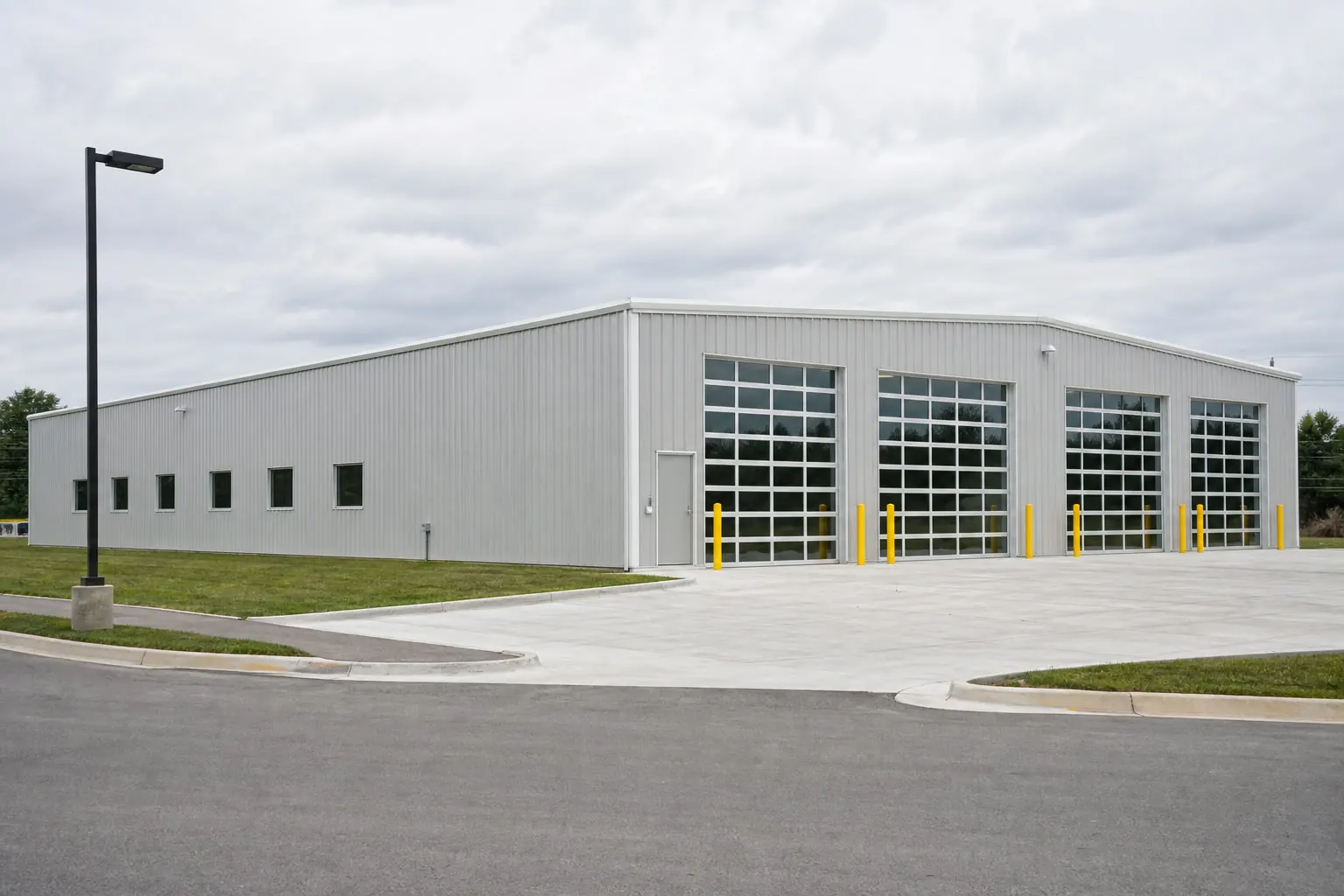
Example
Example Configuration
Get Quotes for a 60×60 Fire and EMS Station Building
Quick dimensions
At a Glance
Width
60 ft across the gable end.
Length
60 ft along the sidewall.
Floor area
3,600 sq ft of clear floor.
Eave height
16 ft at the sidewall on the stored profile.
Use
How a 60×60 Fire and EMS Station Building May Be Used
Assembly space
Clear-span width determines how the main space can be arranged and seated.
Support rooms
Ancillary rooms are commonly placed along one side or at one end.
Access and egress
Entrance and exit placement follows the occupancy requirements for the use.
Acoustics and finish
Interior treatment is specified with the intended activity in mind.
Configuration
How This Building Is Configured
Configuration summary
| Building type | Fire and EMS Station Building |
|---|---|
| Footprint | 60 ft × 60 ft |
| Floor area | 3,600 sq ft |
| Eave height | 16 ft |
Planning
Footprint & Space Planning
Footprint
Width and length are chosen together: width is usually fixed by what has to fit side by side, length by how many bays are needed.
Height
Eave height affects door options, storage height and how open the interior feels.
Access
Where vehicles and people enter changes the whole interior layout, so access is settled before anything else.
Doors and openings
Opening width, height and position are specified with the supplier; they affect the frame and the wall bracing.
Site
Slope, drainage, access for delivery and erection, and the foundation are confirmed for the actual property.
Expansion
Extending along the length is usually simpler than changing the width later, which is worth deciding up front.
Access
Doors & Access Considerations
Opening width
Across a 60 ft gable end, the practical opening width is limited by the frame and confirmed with the supplier.
Opening height
A 16 ft eave sets the ceiling on door height before any frame change.
Drive-through
Matching openings at both ends avoid reversing, at the cost of usable wall.
Similar sizes
Other Sizes for a Fire and EMS Station Building
60′ × 40′
2,400 sq ft
60′ × 80′
4,800 sq ft
50′ × 60′
3,000 sq ft
Related
Related Building Types
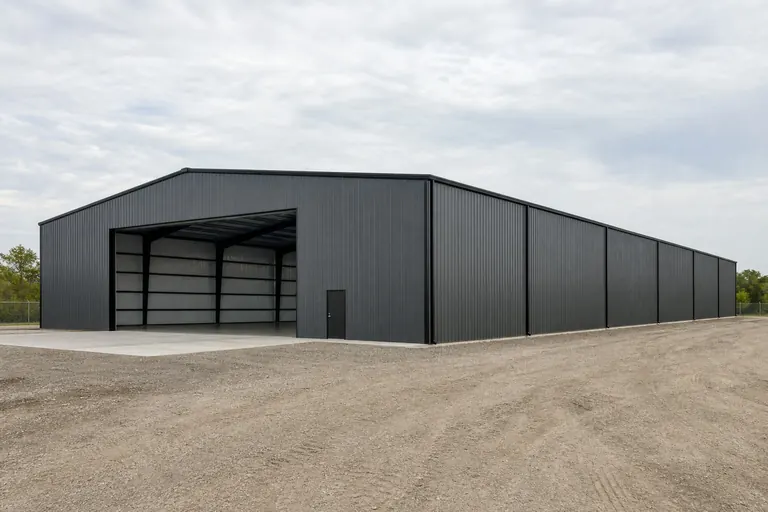
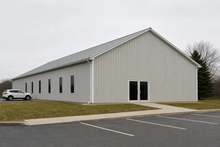
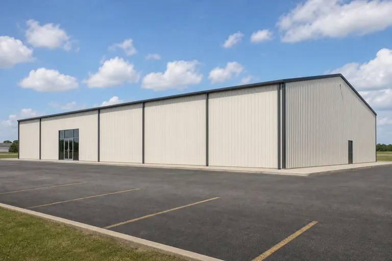
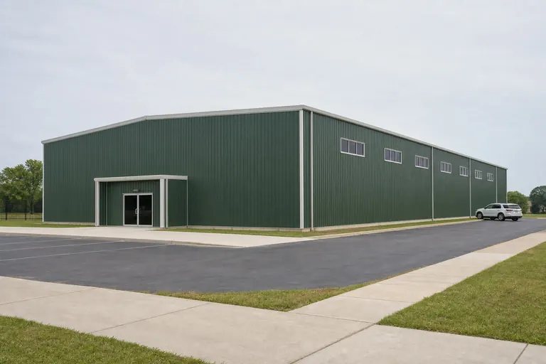
Example configuration — for planning purposes only.
FAQ
Common Questions
60 ft × 60 ft is 3,600 square feet of floor area before any interior partitions.
Length is usually adjusted in bay increments, and width is a larger design change. Both are confirmed with the supplier for the final design.
Site preparation, foundation and erection are commonly quoted separately from the building package. Confirm the scope of any quote you receive.
Compare nearby sizes
Related footprints for this building type
Each page works through one footprint for one building type.
Cost drivers
Quantities that move the estimate at 60x60
Quantities, not prices, are publishable here: roof cladding runs 3,795 square feet — 5% above the 3,600-square-foot floor at a 4:12 pitch — with 55.6 cubic yards of nominal slab beneath it. Depth is bought cheaply and width expensively, which is why this proportion tends to be argued about before anything else.
Proportion drives cost here as much as size does: 240 ft of wall around 3,600 sq ft is 0.067 ft of wall per enclosed square foot, and a squarer plan of the same area would carry less. What moves the figure further on a a volunteer station members drive to and park apparatus in, entering and exiting through the same bay front is the fit-out volunteer fire station layout implies, along with framed openings and the height chosen for the 60 ft span.
- apparatus door height and width
- drive-through bays versus reverse-in bays
- exhaust capture in the bays
- crew quarters as a separate conditioned envelope
Overview
A 60x60 fire and ems station building planned as a volunteer station members drive to and park apparatus in, entering and exiting through the same bay front
This page is ordered around quarters buffer, because that is the decision this footprint settles first and every later choice follows from it.
The footprint holds 4 apparatus bays — 4 across by 1 deep — and leaves 12 feet of depth for a gear and turnout area between the bays and the day room, so members suit up close to the apparatus rather than carrying gear across the building.
Efficiency is the useful number here: 900 square feet of enclosed floor per apparatus bay, against a 476-square-foot module. That is generous — the footprint is doing more than hold modules. The corner nobody plans for is the one that fills first, which is an argument for planning it.
A 60 by 60 footprint is a near-square plan: 3,600 sq ft enclosed by 240 ft of wall, at a 1:1 length-to-width proportion. Along its 60 ft dimension it takes 1 run of apparatus bays at 34 ft, leaving 26 ft over — the 26 ft is where the argument about this size actually happens. Taken purely as arithmetic, 60 by 60 gives 3 apparatus bays across the 60 ft dimension once 14 ft is reserved for movement, and 1 deep along the 60 ft dimension. Run as a a volunteer station members drive to and park apparatus in, entering and exiting through the same bay front, 4 ft across is below the 10 ft this use needs to be worth planning, so there is no turnout area between the bays and the day room, so gear is staged wherever there is a wall left over and members cross the bay floor to reach it How apparatus enters and exits governs the plan more than the number of bays does — a drive-through approach and a single-entry approach solve different problems.
This footprint is planned as a volunteer station members drive to and park apparatus in, entering and exiting through the same bay front. At 1:1 the plan is close enough to square that neither width nor depth is doing the arguing; what decides the layout here is where the openings go, because no proportion is forcing a direction on the floor. Spent as a square 60 by 60 instead, the same 3,600 sq ft would stand 3 apparatus bays across rather than 3, and would trade this plan's length for parallel access. That is the width-against-depth decision this footprint has already made. This is the scale at which informal habits start to fail: two people working at once need the routes named on the plan rather than agreed by memory. Arrivals are staggered and individual rather than simultaneous, so the building has to work for one person as well as for a full roster. A layout that only makes sense with every position filled fails on the calls where it matters most, which are often the ones with the fewest members responding. Clearance in the apparatus bay follows the tallest apparatus expected to be housed there, not the ceiling height anywhere else in the building.
Areas, perimeter, roof area, ridge height, slab volume and the apparatus bay counts on this page are computed from the stored 60x60 record and this platform's planning module for the fire and ems station building category.
Allocation
Dividing the floor for a volunteer station members drive to and park apparatus in, entering and exiting through the same bay front
The staffing and turnout pattern this station could equally be planned for is a continuously staffed station with living quarters separated from the apparatus floor: there is no buffer between quarters and the bay, so noise, exhaust and traffic from the apparatus floor reach the living space directly. The bay front takes the width the apparatus needs to enter directly, a gear and turnout strip runs along the wall nearest the bays, and the day room or meeting space sits behind that strip rather than beside the apparatus. Keeping meeting space out of the bay's sightline is what keeps the building usable between calls.
Depth arithmetic leaves a working end zone here. 720 square feet sits past the last row, which is why 60x60 tends to be planned with a gear and turnout area between the bays and the day room, so members suit up close to the apparatus rather than carrying gear across the building designed in rather than added later. What the building holds in its busiest week is the honest brief; the rest of the year is slack.
Spare width is the more valuable of the two leftovers here: a continuous 4-foot strip beats the same area stranded at the end of the run, because it touches every position along the way. Plan the exit as carefully as the entrance; buildings are emptied under more time pressure than they are filled.
At 1:1 the plan is close enough to square that neither width nor depth is doing the arguing; what decides the layout here is where the openings go, because no proportion is forcing a direction on the floor. Spent as a square 60 by 60 instead, the same 3,600 sq ft would stand 3 apparatus bays across rather than 3, and would trade this plan's length for parallel access. That is the width-against-depth decision this footprint has already made. This is the scale at which informal habits start to fail: two people working at once need the routes named on the plan rather than agreed by memory. Arrivals are staggered and individual rather than simultaneous, so the building has to work for one person as well as for a full roster. A layout that only makes sense with every position filled fails on the calls where it matters most, which are often the ones with the fewest members responding. Clearance in the apparatus bay follows the tallest apparatus expected to be housed there, not the ceiling height anywhere else in the building. That movement pattern, not the 3,600-square-foot total, is what decides whether the leftover 12 feet is useful here.
Height
Interior height for a 60x60 fire and ems station building
The stored configuration carries a 16-foot eave and computes to 26 feet at the ridge on a 4:12 pitch — a 10-foot rise across 60 feet. Height is therefore not uniform, and the sidewall is the constraint. Insulating later is possible; framing for insulation later is much harder.
Clearance is set by the tallest apparatus expected to occupy the bay, not by the day-room ceiling, and that clearance should be confirmed before the building is planned around a specific truck. Storage above the bays, where clearance allows, is space that would otherwise sit unused.
Ventilation across 3,600 square feet at this height: exhaust capture in the bays is planned as part of the building rather than added afterwards.
Clear height below purlins, bracing and lighting is lower than the eave height. The usable figure comes from the manufacturer's framing for the selected building.
Configurations
Configuring 4 apparatus bays at 60x60
Nominal bay division computes to 3 bays at about 20 feet, wider than the 14-foot module — so a position can sit inside a bay without a frame line splitting it. Interior divisions are the last decision that should be fixed, because they are the first one that usually changes.
A single row means nothing is trapped: every position faces the opening directly, which is this footprint's advantage over a deeper building of the same width. Utilities entering on the wrong elevation quietly rewrite the interior layout.
A second bay is added beside the first rather than behind it, preserving the direct-entry approach; extending a bay backward turns a drive-through arrangement into one that requires reversing, which undoes the original planning advantage.
Configured as a volunteer station members drive to and park apparatus in, entering and exiting through the same bay front, 60x60 is judged on whether the 4 apparatus bays it holds match the operation, and on whether the 4 feet of spare width leaves the route this mode depends on.
- Does the work need four lanes across, or two lanes flanking an interior work hall, or does it need a second lane that this 60-foot span cannot give?
- Is the 60-foot length being bought for depth, or for the repeated bays — five or six repeated bays, so functions are assigned bay by bay?
- Is the tallest apparatus dimension measured with everything mounted?
- Drive-through or reverse-in, and what does the apron allow?
Bay division shown here is a planning module computed from the stored length. Actual bay spacing is set by the manufacturer's frame design for the building.
Openings
Openings for 4 apparatus bays across
The 60-foot gable can carry 4 openings, one per apparatus bay, with 4 feet of wall left for piers between and beside them — the arrangement that keeps each position independently reachable. Long spans buy flexibility that is only worth paying for if the operation actually changes shape.
The 60 ft ends and the 60 ft sides offer very different opening budgets: 60 ft of end wall has room for one wide opening or two modest ones, while 60 ft of side wall can carry several without the openings competing. On this plan the deciding factor is whether volunteer fire station layout or apparatus bay planning should be the first thing reached from the door.
Framed-opening sizes, headers and the structure around them are engineered for the specific building. Confirm every opening with the door supplier and the building manufacturer before ordering.
Usable area
How the 3,600 square feet divides at 60x60
Computed apparatus bay fit for a 60x60 fire and ems station building
| Measure | Computed at this footprint |
|---|---|
| Apparatus bays across the 60-foot width | 4 at a 14-foot module |
| Leftover width | 4 ft (240 sq ft as a full-length strip) |
| Rows along the 60-foot length | 1 at a 34-foot module after 14 ft of circulation |
| Leftover depth | 12 ft (720 sq ft across the width) |
| Total apparatus bays | 4 |
| Share of floor committed | 53% |
Module footprint used here is 14 by 34 feet, this platform's planning module for a fire and ems station building. It is not a code minimum or an engineered clearance.
Example allocation of the 60-foot length — planning model, not survey data
| Zone | Length along the building | Computed area |
|---|---|---|
| Primary operating area | 36 ft | 2,160 sq ft |
| Customer or staff area | 13.2 ft | 792 sq ft |
| Back of house and utility | 10.8 ft | 648 sq ft |
Shares applied to the stored 60-foot length; areas computed against the 60-foot width.
Module footprints and allocation shares come from this platform's use typology and are published as example planning models. They are not recommendations and do not describe a majority of projects.
Comparison
What changes at adjacent footprints
Computed comparison of nearby footprints for a fire and ems station building
| Footprint | Floor area | Apparatus bays |
|---|---|---|
| 36x40 | 1,440 sq ft | 0 (2 x 0) |
| 24x60 | 1,440 sq ft | 1 (1 x 1) |
| 30x50 | 1,500 sq ft | 0 (1 x 0) |
| 40x40 | 1,600 sq ft | 0 (2 x 0) |
| 36x48 | 1,728 sq ft | 0 (2 x 0) |
Areas computed from each stored size record; apparatus bay counts computed with the same 14 by 34 foot planning module.
- 36x40 moves the count from 4 to 0 apparatus bays (2 across by 0 deep), which is the reason to choose between them.
- 24x60 moves the count from 4 to 1 apparatus bays (1 across by 1 deep), which is the reason to choose between them.
- 30x50 moves the count from 4 to 0 apparatus bays (1 across by 0 deep), which is the reason to choose between them.
Nearby footprints read for a fire and ems station building: exact change in area and in planning apparatus bays
| Footprint | Area Δ | % Δ | Apparatus bays at that footprint | What changes for this use |
|---|---|---|---|---|
| 50x80 | +400 sq ft | +11.1% | 3 (3 x 1) | −1 apparatus bay on the same planning module. |
| 40x80 | −400 sq ft | −11.1% | 2 (2 x 1) | −2 apparatus bays on the same planning module. |
| 50x60 | −600 sq ft | −16.7% | 3 (3 x 1) | −1 apparatus bay on the same planning module. |
| 60x80 | +1,200 sq ft | +33.3% | 6 (3 x 2) | +2 apparatus bays on the same planning module. |
Areas are arithmetic on two stored size records; apparatus bay counts use this platform's 14 by 34 foot planning module and are not a capacity statement.
Because this footprint is planned as a volunteer station members drive to and park apparatus in, entering and exiting through the same bay front, the useful next reads are different from the ones a differently shaped fire and ems station building suggests: volunteer fire station layout, apparatus bay planning, turnout gear area.
Visualization
Reading the 60x60 footprint as a fire and ems station building
FAQ
Questions about 60x60 fire and ems station building projects
3,840 square feet of wall and 3,795 square feet of roof at a 4:12 pitch — the roof exceeding the floor by 5%.
Reserving 14 ft across the 60 ft dimension for movement leaves 46 ft of working width, which takes 3 apparatus bays at 14 ft. Along 60 ft it takes 1 runs at 34 ft. That is 3 positions out of 3,600 sq ft, and the remainder is circulation, walls and the margin every plan needs. Whether that count is enough depends on when a member arrives alone, can they park a personal vehicle, reach turnout gear and board the apparatus without crossing another member's path. These are planning figures computed from the footprint, not a quoted layout.
The width leaves 4 feet spare after 4 apparatus bays. That margin absorbs wall storage and passing room. Width is the dimension that cannot be extended later.
Not necessarily. Many volunteer stations plan a compact meeting and gear area rather than a full living space, since staffing and occupancy patterns for the specific department are set locally rather than by the building's size.
Length here buys 1 row and 3 nominal bays; width buys 4 positions side by side. At this aspect ratio both dimensions are still adding usable positions.
Methodology
How this page was produced
Sources and methodology
Find Steel Buildings dimensional records
Find Steel Buildings · Primary platform dataset · Tier 1 — code authority, standards body, primary dataset or manufacturer engineering
Supports: Stored nominal width, length, eave height, roof pitch and slab thickness for this subject.
International Building Code and International Residential Code
International Code Council · Model code · Tier 1 — code authority, standards body, primary dataset or manufacturer engineering
Supports: The framework of adopted codes and local amendments that decides permitting, separation and opening requirements. Cited as the governing framework, never as a local requirement.
- Dimensional figures: Width, length, eave height, roof pitch and nominal slab thickness come from this platform's stored record for the subject. Floor area, perimeter, wall area, roof area, ridge height and slab volume are computed from those inputs rather than transcribed.
- Apparatus bay fit: Counts, leftover strips and per-module areas are computed from the stored 60x60 record against this platform's 14 by 34 foot planning module for the fire and ems station building category, with 14 feet allowed for circulation. The module is editorial planning typology, not a code minimum or an engineered clearance.
- Allocation model: Zone shares come from this platform's use typology for commercial and customer-facing operations and are applied arithmetically to the stored 60-foot length.
- Allocation and layout models: Layout splits are arithmetic on the stored footprint, published as example allocation models. They are not survey findings and do not describe what buyers most often choose.
- Clearance and opening guidance: Clearance and opening statements are planning guidance. Final dimensions depend on the selected door system, header detail and the manufacturer's engineering for the building.
Methodology notes
- Prices: No price figure appears on this page. Cost data is published on this platform only with a documented inclusion basis, a collection date and a named source.
Drawn to scale
Plans and dimensions
Every drawing below is generated from the exact dimensions for this building, so proportions and areas are accurate.
Compare 60x60 fire and ems station building configurations
Review the allocation models for this footprint side by side, then estimate the configuration you intend to build.